The J30J series connectors offer a diverse range of locking components, categorized by mounting methods and application scenarios. Different components vary significantly in installation position, adaptation objects, and usage requirements, with most requiring matching with specific auxiliary components. Below is a detailed introduction to various locking components and their core features:
- These three types mostly serve as auxiliary supporting locking components, often used in conjunction with the mainstream P-series locking components. The K1 type is particularly special, compatible only with the P1-type locking component. In contrast, the L and K types have broader adaptability, capable of matching multiple P-series components such as P, P0, and P3. They are suitable for certain modified versions of J30J products; for example, the J30J-C series can only be paired with L, K, and K1-type locking components, ensuring connection stability when the outlet direction of the connector is 90° to the insertion direction.
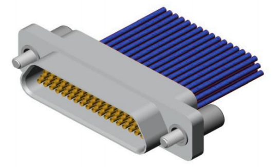 L type
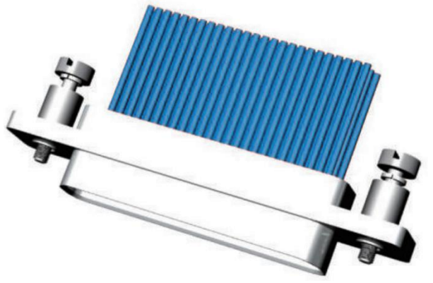 K type
- Types P, P8, and P9: Exclusive to front-panel mounting, they must be used with L or K-type locking components. In terms of adaptability, J30J products with anti-rotation slots or shielded cable clamps (such as the J30J-D series and J30J-AD series) can only be matched with these locking components. The anti-rotation design of their shell flanges prevents screws from rotating during installation, improving mounting accuracy.
- Type P1: Also a front-panel mounting adapter component, its core feature is the exclusive matching with the K1-type locking component. This differentiates it from the matching rules of P, P8, and P9 types, meeting assembly precision requirements in specific scenarios.
- Types P5 and P10: Specifically designed for straight plug printed circuit boards (PCBs), they are only suitable for front-panel mounting scenarios with compatible PCB thicknesses and must be used with L or K-type locking components. They adapt to connectors with various contact counts (9–100 contacts), fulfilling the installation needs of straight plug PCBs.
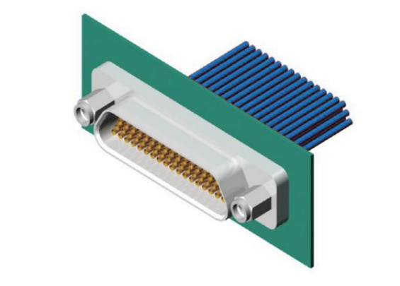 P type Front-panel
- Types P0, P3, P4, and P11: General-purpose rear-panel mounting locking components, requiring pairing with L or K-type components. For plugs (sockets) with cable clamp assemblies, the mounting panel thickness should be adjusted according to the formula "mounting panel thickness + 0.7" to avoid the cable clamp affecting installation fit. They are suitable for most conventional rear-panel mounting scenarios.
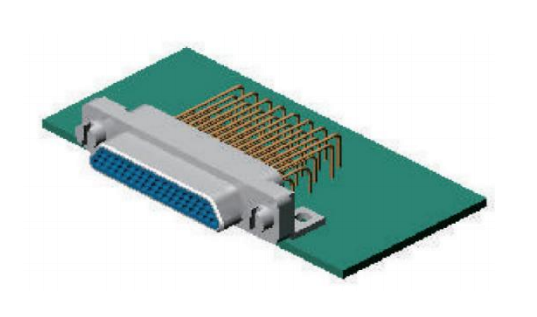
- Type P2: Has strict installation restrictions, applicable only to 1mm-thick mounting panels and rear-panel mounting of 90° bent plug PCBs, requiring matching with L or K-type components. It adapts to connectors with 9–100 contacts, focusing on specialized mounting scenarios for bent plug PCBs with thin mounting panels.
- Type P14: Suitable for 3mm-thick mounting panels, also used for rear-panel mounting of 90° bent plug PCBs and paired with L or K-type components. It forms a thickness-differentiated adaptation with the P2 type, covering the mounting needs of bent plug PCBs with different panel thicknesses.
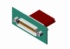 P type Rear-panel
- Type P7: Specifically designed for 90° bent plug PCBs, exclusive to front-panel mounting and requiring matching with L or K-type components. It adapts to various contact count specifications, filling the specialized locking demand for front-panel mounting of bent plug PCBs.
- Types V and V1: Both used in scenarios where strong locking is not required. The V type is suitable for PCBs with a thickness not exceeding 2.5mm and only applicable to J30J standard straight plug PCB products without locking requirements. The V1 type follows a similar non-locking adaptation logic, meeting the needs of low-intensity fixation, frequent disassembly, or light-duty connection scenarios.
 V type

 L type
 K type
 P type Front-panel
 P type Rear-panel
 V type